
You are using an out of date browser. It may not display this or other websites correctly.
You should upgrade or use an alternative browser.
You should upgrade or use an alternative browser.
Failsafe setup -AFR and Oil pressure safeties
- Thread starter Turbo 6
- Start date
For fuel pressure, you need a fuel pressure sensor, that is set up in the Generic sensor inputs, calibrated in KPA. Remember the sensor # you used. Set the lag factor low, like 15, which will help smooth out the reading.
Then go to the Fuel Pump and Pressure dialog under the Fuel Settings menu.
Turn on the Fuel Sensor Input by selecting the sensor # you used for the fuel pressure sensor (mine is sensor 6).
Below that, set the sensor type to "gauge", which is the typical style.
Now the ECU is monitoring fuel pressure, but we still have to set up the safety.

Setting up the Fuel Pressure safety...
Go to the Fuel Pressure Safety dialog under Fuel Settings
Set up the screen like this picture below as a starting point.
It will start monitoring over 150kpa (about 7psi boost), and 3000rpm. If fuel pressure drops more than 5psi from target, for more than 1 second, the safety is tripped.

Keep in mind that fuel pressure can pulse quite a bit on some setups, and you might need to install an orifice (.030-.050") at the pressure sensor to dampen the pulses, or it might trip the safety falsely.
What happens when the safety is tripped is dictated on the AFR Safety System dialog. See below.
I have the AFR Safety turned off in this example, as I just want you to focus on the part circled in red.
Those parameters are what happens when any of the safeties are tripped (fuel psi, AFR, or oil pressure).
For the stock ignition, leave the spark kill at 0.0, since it won't work. It will work with other ignitions like the direct coilpack (truck), or coil per plug.
The other parameters show when to turn the fuel back on.

If you trip the fuel pressure safety, it will show up in a log under "CEL Status" as "8192".
Next post will be AFR Safety.
Then go to the Fuel Pump and Pressure dialog under the Fuel Settings menu.
Turn on the Fuel Sensor Input by selecting the sensor # you used for the fuel pressure sensor (mine is sensor 6).
Below that, set the sensor type to "gauge", which is the typical style.
Now the ECU is monitoring fuel pressure, but we still have to set up the safety.
Setting up the Fuel Pressure safety...
Go to the Fuel Pressure Safety dialog under Fuel Settings
Set up the screen like this picture below as a starting point.
It will start monitoring over 150kpa (about 7psi boost), and 3000rpm. If fuel pressure drops more than 5psi from target, for more than 1 second, the safety is tripped.
Keep in mind that fuel pressure can pulse quite a bit on some setups, and you might need to install an orifice (.030-.050") at the pressure sensor to dampen the pulses, or it might trip the safety falsely.
What happens when the safety is tripped is dictated on the AFR Safety System dialog. See below.
I have the AFR Safety turned off in this example, as I just want you to focus on the part circled in red.
Those parameters are what happens when any of the safeties are tripped (fuel psi, AFR, or oil pressure).
For the stock ignition, leave the spark kill at 0.0, since it won't work. It will work with other ignitions like the direct coilpack (truck), or coil per plug.
The other parameters show when to turn the fuel back on.
If you trip the fuel pressure safety, it will show up in a log under "CEL Status" as "8192".
Next post will be AFR Safety.
AFR Safety
Here's an example of how you could set up the AFR Safety. The numbers in the table are how much leaner than target AFR is allowed.
For example, I have it set to .6 in the higher boost areas. If my target AFR is 11.0, then the actual AFR would have to go leaner than 11.6, for 1.0 second, before the AFR Safety is tripped. It also doesn't start checking until 150kpa and 3500rpm. Since I'm not checking until 150kpa, then everything in the table below 150kpa is doing nothing.
You can experiment with tighter settings, but you have to be careful about tripping the safety with normal AFR variations.

If the AFR Safety is tripped, and you have a log, it will show in the "CEL Status" as "32" which is AFR Fault. But if it also shuts down the engine, thats "AFR Shutdown" which is "32768". It may add those 2 together.
Next is Oil Pressure.
Here's an example of how you could set up the AFR Safety. The numbers in the table are how much leaner than target AFR is allowed.
For example, I have it set to .6 in the higher boost areas. If my target AFR is 11.0, then the actual AFR would have to go leaner than 11.6, for 1.0 second, before the AFR Safety is tripped. It also doesn't start checking until 150kpa and 3500rpm. Since I'm not checking until 150kpa, then everything in the table below 150kpa is doing nothing.
You can experiment with tighter settings, but you have to be careful about tripping the safety with normal AFR variations.
If the AFR Safety is tripped, and you have a log, it will show in the "CEL Status" as "32" which is AFR Fault. But if it also shuts down the engine, thats "AFR Shutdown" which is "32768". It may add those 2 together.
Next is Oil Pressure.
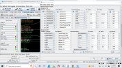
Oil Pressure Safety
You will need to have an oil pressure sensor connected and calibrated in PSI in the Generic sensor inputs. Remember what # sensor you are using.
Here's an example of how you could set up the Oil Pressure Safety.
This screen is under the Advanced Engine menu.
If you don't see the settings below the table, press the little button with the 3 dots (circled in red).
Set the sensor input to the # of the sensor you set up.
"Oil pressure Warning" is if you want to connect a separate light.
I would leave limp mode off.
So in this example, the oil pressure would have to go below the settings in the table, for 1.0 second, and the engine would shut down.

If the Oil Pressure Safety is tripped, and you have a log, it will show in the "CEL Status" as "4096" which is Oil Fault.
You will need to have an oil pressure sensor connected and calibrated in PSI in the Generic sensor inputs. Remember what # sensor you are using.
Here's an example of how you could set up the Oil Pressure Safety.
This screen is under the Advanced Engine menu.
If you don't see the settings below the table, press the little button with the 3 dots (circled in red).
Set the sensor input to the # of the sensor you set up.
"Oil pressure Warning" is if you want to connect a separate light.
I would leave limp mode off.
So in this example, the oil pressure would have to go below the settings in the table, for 1.0 second, and the engine would shut down.
If the Oil Pressure Safety is tripped, and you have a log, it will show in the "CEL Status" as "4096" which is Oil Fault.
Eric-
will this only work with a 3 wire .5>4.5 Sensor or will a one wire Oil pressure sending unit work -I have an autometer electric oil pressure gauge with one wire sending unit in operation now on generic sensor 10 spot ( can ADC03)
 www.autometer.com
will this only work with a 3 wire .5>4.5 Sensor or will a one wire Oil pressure sending unit work -I have an autometer electric oil pressure gauge with one wire sending unit in operation now on generic sensor 10 spot ( can ADC03)
2-1/16" OIL PRESSURE, 0-100 PSI, AIR-CORE, ES
5927 Gauge, Oil Pressure, 2 1/16", 100 PSI, Electric, ES
www.autometer.com
Last edited:
turbo nasty
Active Member
Not going to work as that sender simply reads resistance to ground for the needle movement or your gaige. Your going to need a transducer style sender separate to send signal to ecugnEric-
I'm using the VDO 1 wire sending unit on sensor 10 and trying to figure out what values to put in the 0V and 5V settings fields. any ideas?
Ok. So as far as gauges go, I have a scan master g and was going to add a boost gauge. I set up the Mac valve so the ecu controls boost. Is there any other critical gauge I should add to keep an eye for safety? I also have fuel pressure and oil pressure on transducers to ecu.It would work the same as gasoline.
MCH86GN
Active Member
This response is a little late, but the resistance to ground measure can only be determined by the voltage drop. I have wrote transfer functions for many different A2D inputs and whether they are current measurement or resistance measure the analog to digital converter still reads an input voltage. Typically the reference voltage for the input signal is 5v, although I did work on a project about ten years ago where the reference voltage was 8v.Not going to work as that sender simply reads resistance to ground for the needle movement or your gaige. Your going to need a transducer style sender separate to send signal to ecugn
turbo nasty
Active Member
This is a way over complicated angle. It's the wrong sensor he was trying to use....simple one wire sender not a transducer, etc.This response is a little late, but the resistance to ground measure can only be determined by the voltage drop. I have wrote transfer functions for many different A2D inputs and whether they are current measurement or resistance measure the analog to digital converter still reads an input voltage. Typically the reference voltage for the input signal is 5v, although I did work on a project about ten years ago where the reference voltage was 8v.
MCH86GN
Active Member
I wasn't trying to over complicate the matter, just trying to act like I am "smart". I am always saying how much it bothers me when people try to use $40 words to explain 10 cent concepts. What a hypocrite!This is a way over complicated angle. It's the wrong sensor he was trying to use....simple one wire sender not a transducer, etc.